by Teffin Varghese | Jun 10, 2017 | Howtos, Linux, Networking, OS, Servers, Storages, Troubleshooting

Distributed Replicated Block Device (DRBD)
DRBD is a distributed replicated storage system for the Linux platform. It is implemented as a kernel driver, several user space management applications, and some shell scripts. DRBD is traditionally used in high availability (HA) computer clusters, but beginning with DRBD version 9, it can also be used to create larger software defined storage pools with a focus on cloud integration.
Comparison to RAID-1
=====================
DRBD bears a superficial similarity to RAID-1 in that it involves a copy of data on two storage devices, such that if one fails, the data on the other can be used. However, it operates in a very different way from RAID and even network RAID.
In RAID, the redundancy exists in a layer transparent to the storage-using application. While there are two storage devices, there is only one instance of the application and the application is not aware of multiple copies. When the application reads, the RAID layer chooses the storage device to read. When a storage device fails, the RAID layer chooses to read the other, without the application instance knowing of the failure.
In contrast, with DRBD there are two instances of the application, and each can read only from one of the two storage devices. Should one storage device fail, the application instance tied to that device can no longer read the data. Consequently, in that case that application instance shuts down and the other application instance, tied to the surviving copy of the data, takes over.
Conversely, in RAID, if the single application instance fails, the information on the two storage devices is effectively unusable, but in DRBD, the other application instance can take over.
How it Works
============
The tool is built to imperceptibly facilitate communication between two servers by minimizing the amount of system resources used- It therefore does not affect system performance and stability.
DRBD facilitates communication by mirroring two separate servers- one server, although passive, is usually a direct copy of the other. Any data written to the primary server is simultaneously copied to the secondary one through a real time communication system. Any change made on the data is also immediately replicated by the passive server.
The passive server only becomes active when the primary one fails and collapses. When such a failure occurs, DRBD immediately recognizes the mishap and shifts to the secondary server. This shifting process however, is optional- it can either be manual or automatic. For users who prefer manual, one is required to authorize the system to shift to the passive server when the primary one fails. Automatic systems on the other hand, swiftly recognize problems within the primary servers and immediately shift to the secondary ones.
DRBD installation
=================
Install ELRepo repository on your both system:
———————————————-
# rpm -Uvh http://www.elrepo.org/elrepo-release-6-6.el6.elrepo.noarch.rpm
Update both repo
————————
yum update -y
setenforce 0
Install DRBD
—————–
[root@server1 ~]# yum -y install drbd83-utils kmod-drbd83
[root@server1 ~]# yum -y install drbd83-utils kmod-drbd83
Insert DRBD module manually on both machines or reboot
———————————————————————————
/sbin/modprobe drbd
Partition DRBD on both machines
———————————————-
[root@server1 ~]# fdisk -cu /dev/sdb
[root@server2 ~]# fdisk -cu /dev/sdb
Create the Distributed Replicated Block Device resource file
————————————————————————————-
[root@server1 ~]# vi /etc/drbd.d/clusterdb.res
resource clusterdb
{
startup {
wfc-timeout 30;
outdated-wfc-timeout 20;
degr-wfc-timeout 30;
}
net {
cram-hmac-alg sha1;
shared-secret sync_disk;
}
syncer {
rate 10M;
al-extents 257;
on-no-data-accessible io-error;
}
on server1 {
device /dev/drbd0;
disk /dev/sdb1;
address 192.165.1.111:7788;
flexible-meta-disk internal;
}
on server2 {
device /dev/drbd0;
disk /dev/sdb1;
address 192.165.1.111:7788;
meta-disk internal;
}
}
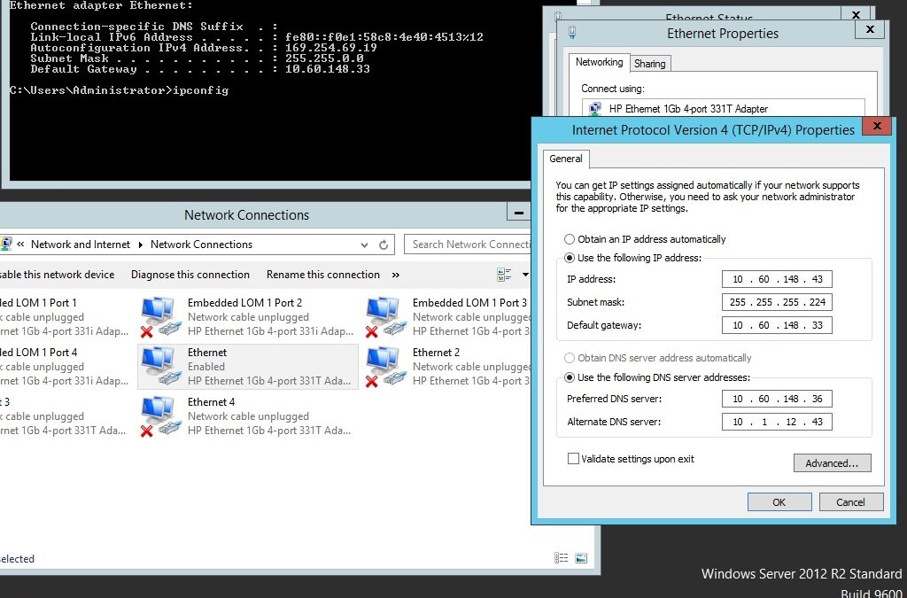
Make sure that DNS resolution is working
———————————————————-
/etc/hosts
192.168.1.110 server1 server1.example.com
192.168.1.111 server2 server2.example.com
Set NTP server and add it to crontab on both machines
—————————————————————————–
vi /etc/crontab
5 * * * * root ntpdate your.ntp.server
Copy DRBD configured and hosts file to server2
——————————————————————-
[root@server1 ~]# scp /etc/drbd.d/clusterdb.res server2:/etc/drbd.d/clusterdb.res
[root@server1 ~]# scp /etc/hosts server2:/etc/
Initialize the DRBD meta data storage on both machines
—————————————————————————–
[root@server1 ~]# drbdadm create-md clusterdb
[root@server2 ~]# drbdadm create-md clusterdb
Start the drdb on both servers
——————————————–
[root@server1 ~]# service drbd start
[root@server2 ~]# service drbd start
On the PRIMARY server run drbdadm command
——————————————————————
[root@server1 ~]# drbdadm — –overwrite-data-of-peer primary all
Check if Device disk initial synchronization to complete (100%) and check to confirm you are on primary server
———————————————————————————————————————————————————–
[root@server1 yum.repos.d]# cat /proc/drbd
version: 8.3.16 (api:88/proto:86-97)
GIT-hash: a798fa7e274428a357657fb52f0ecf40192c1985 build by phil@Build32R6, 2013-09-27 15:59:12
0: cs:SyncSource ro:Primary/Secondary ds:UpToDate/Inconsistent C r—–
ns:78848 nr:0 dw:0 dr:79520 al:0 bm:4 lo:0 pe:0 ua:0 ap:0 ep:1 wo:f oos:2017180
[>………………..] sync’ed: 27.0% (2037180/2096028)K
finish: 0:02:58 speed: 11,264 (11,264) K/sec
ns:1081628 nr:0 dw:33260 dr:1048752 al:14 bm:64 lo:0 pe:0 ua:0 ap:0 ep:1 wo:f oos:0]
Create filesystem on Distributed Replicated Block Device device
——————————————————————————————-
[root@server1 yum.repos.d]# /sbin/mkfs.ext4 /dev/drbd0
mke2fs 1.41.12 (06-June-2017)
Filesystem label=
OS type: Linux
Block size=4096 (log=2)
Fragment size=4096 (log=2)
Stride=0 blocks, Stripe width=0 blocks
131072 inodes, 524007 blocks
26200 blocks (5.00%) reserved for the super user
First data block=0
Maximum filesystem blocks=536870912
16 block groups
32768 blocks per group, 32768 fragments per group
8192 inodes per group
Superblock backups stored on blocks:
32768, 98304, 163840, 229376, 294912
Writing inode tables: done
Creating journal (8192 blocks): done
Writing superblocks and filesystem accounting information: done
This filesystem will be automatically checked every 26 mounts or
180 days, whichever comes first. Use tune2fs -c or -i to override.
Now you can mount DRBD device on your primary server
————————————————–
[root@server1 ~]# mkdir /data
[root@server1 ~]# mount /dev/drbd0 /data
You don’t need to mount the disk from secondary machines. All data you write on /data folder will be synced to machine2.
Adios 🙂

by Teffin Varghese | Jun 5, 2017 | Howtos, Linux, OS, Servers, Storages, Troubleshooting
Okay, What is RAID 🙂
RAID (Redundant Array of Independent Disks) is a data storage virtualization technology.
It combines multiple inexpensive,small disk drives into an array of disks in order to
provide redundancy, lower latency and maximized the chance to recover data from the hard drives
If they crashes. And there by improving the performance.
The RAID appears to the system as a single drive.
RAID can be implemented via Hardware devices as RAID controllers or via software
controlled by the Linux Kernel.
The most commonly used RAID levels are
RAID 0 [Minimum of 2 Disk]
RAID 1 [Minimum of 2 Disk]
RAID 5 [Minimum of 3 Disk]
RAID 10 [Minimum of 4 Disk]
==============================================
RAID 1
RAID 1 is also known as “disk mirroring.” With RAID 1, data is copied seamlessly and simultaneously from one drive to another, creating an exact copy or mirror.
If one of the disk on raid array fails, the other can work without issues. It’s the simplest way to implement fault tolerance storage. But it slightly drag the performance.
This is useful when read performance or reliability is more important than the resulting data storage capacity.
The advantages of raid 1 are it offers excellent read speed and a write-speed that is comparable to that of a single drive and if a drive fails, data do not have to be rebuild, they just need to be copied to a new replacement drive.
The main disadvantage of RAID 1 is that the effective storage capacity is only half of the total drive capacity
because all data get written twice and software RAID 1 solutions do not always allow a hot swap of a failed drive.
Configuring RAID level 1 using mdadm.
Install mdadm on your server.
You can use the following commands to installmdadm.
For RHEL/CentOS/Fedora:
=======================
# yum install mdadm
And for Debian/Ubuntu:
=======================
#apt-get update
#apt-get install mdadm
The next step is to create a RAID array. For that create the disk partitions (with the same size) that are going to be the array members as RAID partition.
To create partitions you can use the following commands.
#fdisk -l | grep /dev/sd (This command will list the disks on the server.eg: the disks on the server are sdb & sdc)
Then choose one disk eg: sdb
#fdisk /dev/sdb
Then press ‘n’ for creating a new partition in /dev/sdb. Then press ‘p’ for use it as primary partition.
Enter the partition number. You can use the full size by just pressing two times ‘Enter key’.
Then press ‘t’ to choose the partition type. Then choose ‘fd‘ for Linux raid auto and press ‘Enter Key’ to apply it.
Pressing ‘p’ verify that the partition is created as Linux raid auto detect.
Press ‘w’ to save the changes.
Follow the same instructions to create new partition on /dev/sdc drive with the same partition size.
The next step is to create a RAID 1 sdb1,sdc1 array using command mdadm:
# mdadm –create –verbose –level=1 –raid-devices=2 /dev/md0 /dev/sdb1 /dev/sdc1
xxxxxxxxxx
–create–> create a new RAID device.
–verbose–>print information about its operations.
/dev/md0 is the new RAID device that we want to create.
–level–> defines the RAID level; in our case, RAID 1.
–raid-devices –> It specifies how many disks (devices) are going to be used in the creation of the new RAID device.(here 2 — /dev/sdb1 /dev/sdc1)
xxxxxxxxx
You can verify raid status using the following command.
#cat /proc/mdstat
#mdadm -E /dev/sd[b-c]1
# mdadm –detail /dev/md0
The next step is formatting the partition and creating a file system and mount the partition.
#mkfs.ext4 /dev/md0 –> to format the partition
To mount /dev/md0 to /raid1 perform the below steps.
# mkdir /raid1
# mount /dev/md0 /raid1
# df -H –> you can verify it is mounted or not.
To auto-mount RAID1 on system reboot, need to make an entry in ‘/etc/fstab‘ file.
For that add the following line to the fstab.
/dev/md0 /raid1 ext4 defaults 0 0
Then run ‘mount -a‘ to check whether there are any errors on fstab entry.
Now update /etc/mdadm/mdadm.conf or/etc/mdadm.conf file as follows:
ARRAY /dev/md0 devices=/dev/sdb1,/dev/sdc1 level=1num-devices=2 auto=yes
or
# mdadm –detail –scan >> /etc/mdadm.conf
That’s all for now. 🙂
by Teffin Varghese | Jun 3, 2017 | Networking
BGP stands for Border Gateway Protocol.
When you make a modem connection to your ISP and want to connect to, for instance, www.google.com,
all the routers along the way have to know where to send the packets you’re sending to our Web server,
and the packets from the server have to find their way back to your computer.
For the first few hops, this isn’t much of the problem.
For instance, your computer only knows the packets don’t have a local destination, so they should be sent over the modem connection.
This can continue for a while, but at some point the decision where to send the packet
next becomes more complex than just “local: keep it” / “not local: send it to a smarter router”.
The router making this decision will have to know where to send the packet based on the destination IP address contained in it.
Since IP addresses are distributed fairly randomly around the globe, there aren’t any shortcuts or calculations
that make it possible for the router to decide this for itself.
The only way a router can know where to send a packet, is when another router tells it “send those packets to me,
I know how to deliver them”. The Border Gateway Protocol (BGP) is a protocol that is used between routers to convey this information.
Since the routers that talk BGP to each other aren’t owned by the same organization (that would kind of defeat the purpose of creating global reachability)
this is often called “inter-domain” routing. BGP and Interdomain Routing Terms
AS
—
Autonomous System.
AS Number
———
Autonomous System Number. Each AS has a unique number that is used to identify it in BGP processing.
Autonomous System
—————–
An Autonomous System is a network that has its own routing policy.
In most cases, customers belong to their ISP’s Autonomous System, but multihomed customers obviously have their own routing policy
that is different from either ISP so they must be a separate AS.
BGP
—
Border Gateway Protocol.
EGP
—
Exterior Gateway Protocol: a routing protocol used between organizations/networks. BGP is an EGP, but there is also an older EGP called EGP.
Gateway
——-
Older term for router. Sometimes the word “gateway” is used to describe a system that connects two dissimilar networks or protocols.
IGP
—
Interior Gateway Protocol: a routing protocol used within an organization/network. Examples are RIP, OSPF, IS-IS and EIGRP.
Multihoming
———–
The practice of connecting to two or more ISPs. Most multihomed networks run BGP so the rest of the Internet knows where to send packets for the multihomed network even if one of the connections fails.
Router
1. Any system that will receive packets over one network connection and then forward them to another by looking at the network address inside the packet.
2. A special-purpose system (like a computer, but usually without a screen, keyboard and harddisks) that forwards packets.
Routing Policy
————–
A policy that defines how a network is connected to other networks and how packets are allowed to flow.